How to make

How to make the most different interesting selfmade things.

Wednesday, January 24, 2007

How to Make DIY Christmas Light controller in 5 minutes!


Okay, today we are going try to build a computer controlled Christmas Lights in 5 minutes.
I’ve been rolling around the neighborhood this late November and some people already have
their Christmas lights decorated.

Well I’ve seen many “static” Christmas lights that always stay on. Today, I will show you how
you can customize your Christmas lights by using a PLC,
a Programmable Logic Controller.

You can also check out our wiki version of on our new FREE DIY wiki too.

UPDATE: Wow, Christmas light controllers CAN BE expensive, check out these prices for these controllers


Labels:

How to Make a custom projector screen.


The quest to build a great home theater is one of our recurring themes for Engadget's How-To Tuesdays. And as anyone home theater buff will tell you, any HDTV worth its weight in salt will present its viewer with a 16:9 (1.78:1) aspect ratio display, or in some cases, project a 1.8:1 ratio. For todays How-To, though, we're building one of the holy grails of the home theater: a 2.35:1 widescreen. Yep, that's movie theater widescreen, alright.

The most important component is the screen material. Mom's old bed-sheet just isn't good enough (and is actually quite nast). Most fabric stores carry rolls of material called curtain backing or black-out cloth. It's a light, opaque white material used to make curtains actually block light. Made from cotton and polyester, one side looks like woven cotton while the other looks like it's plastic coated. At our local fabric store it was about $5 per yard and 54-inches wide. When buying your fabric, we suggest buying at least 4-inches wider and longer than your planned screen dimensions to allow room for construction. If you want to build a MECHA-screen, it's available even wider.

Shopping list:
  • (3) 1 x 4 x 96-inch Douglas Fir boards
  • (1) 2 x 2-foot x 13/64 piece of plywood
  • 1-1/8th-inch fine thread drywall screws
  • Staples
  • (3) yards of white curtain blackout cloth
Tools:
  • Drill with Phillips screwdriver bit
  • Saw
  • Staple Gun
  • Hammer
  • Utility knife or scissors
Our 2.35:1 screen is designed to maximize the materials we purchased. We decided to aim for a 104-inch wide, 44-inch tall screen. By placing 1 x 4 boards at the ends of our 8-foot (96-inch) boards, we achieved 103.5-inches of real estate.

The frame is constructed using theater set 'Flat' construction techniques. 1 x 4-inch boards, some plywood and drywall screws will make a very strong frame. We used Douglas Fir because it was easier to find nice straight boards, and it costs about the same as the more brittle (and bent) select pine. (To visually check the board, hold the end and look down the board lengthwise like a gun barrel. Avoid twisted and curving boards.)

To get started, the 1 x 4-inch boards need to be cut to length. Don't forget that 1 x 4-inch wood is actually .75 x 3.5 by the time it gets to you! Our trick for getting them even is to screw the two boards together and cut both ends at once. Screw two of your 8-foot long boards together and just trim the ends so they're perfectly even. Unscrew them and set them aside. Cut around 45 inches off your last board. Screw the two pieces together and trim one end even. Now cut the two boards down to 44 inches at the same time. (Don't hit the screws with your saw!)

You'll need to cut some 1-foot triangles out of the plywood for each corner. If you don't have a saw, you could just have the hardware store cut out 1-foot squares and use a square on each corner. We cut our triangles on a table-saw.

Lay out your wooden frame on a flat surface. The edges of the 44-inch pieces will be against the ends of the 8-foot pieces. To get the frame square, get a helper and a tape measure. Measure diagonally corner to corner. If the two measurements match, it's square.

Place your plywood triangles on the corners. We uses a scrap piece of 1 x 4-inch to place the triangle evenly off the edges.

Use your screw-driving drill to put the drywall screws in a pattern similar to the picture. (It's generally 3 screws in each corner and a couple along the areas the boards join.) You might want to double check the squareness of the frame as you work just to be safe.

When your frame is done, it'll look something like this. Theater flats usually have a cross bar, but for our light wearing application, it's just not needed.

Now you need a CLEAN surface to work on. Lock the dog in another room and lay your blackout material down on the floor. Carpet or a large clean blanket is important to use. Place your new frame (triangles up) on the middle of the material.

Starting in the middle of one of the long sides, wrap the cloth over the frame.

Apply a gentle tension to the edge of the cloth and staple the cloth about 3/4 of an inch from the outer edge of the frame. Work your way completely to one end. Return to the middle and work the other direction. Repeat for the opposite side. Do the same with the short sides. As you work around, evenly tension the cloth so that there will be no wrinkles. Take your time and it should be fine.

In the corners fold the material over itself and staple everything down.

If the fabric came out nice and even, go ahead and tap all the staples snugly into the wood with a light hammer. Don't hammer so hard that you cut the fabric in the process, you just want the spread the tension of the staple across the fabric.

When you're done, trim the extra material with a utility knife or scissors. Be careful and don't slip and cut your new screen.

Now that the screen is built, mounting depends on you. I used two brass shelf mounting tabs and drywall screws. Just locate some studs (our are part of a cloth covered frame behind the screen). and screw the tab to the back of the frame, and run a drywall screw through the mounting hole. Voila! Total bill of materials: about $35 US

Labels: , ,

How to make a cool DIY Dry Erase Board


Elephant Staircase has a nice tutorial on how to make your own Dry Erase Board. It's super simple and requires a few things of the likes: acrylic plastic sheet, washers, wall anchors. All of which is readily available at your local hardware shop.

The article is pretty detailed and also analyzes the other modes of creating a erase board. You might want to try it on a weekend. Takes about an hour to complete. And there is nothing like using your homemade Erase board.


Labels:

Tuesday, January 23, 2007

How to build a six-axis 3D controller


Three Blind Mice Part 1

I've been exploring 3D graphics using VVVV. One of the things you quickly learn when working in 3D is that doing anything with a 2D mouse is a pain. Particularly I found I was spending a lot of time shuffling the camera position which involves a tricky combination of keystrokes and mouse movements. I wanted to get a camera control that would allow me to fly the camera smoothly in 3D space.

Looking for "3D Mice" in Google found a variety of more-or-less ugly and expensive commercial options, but also this project linked off Slashdot. Humm I thought, how hard could that be to copy.

Mk 1
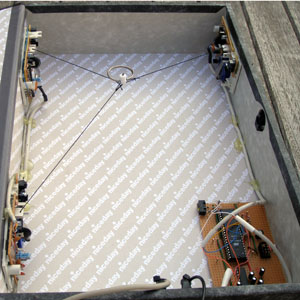
The basic principle of Three Blind Mice is to run three threads round three rollers from old mechanical mice. By using the mouse reports to calculate the length of the extended thread this allows the position where all the threads join to be calculated. First job was to interface the mice to a PC. I am using old Microsoft Itellimice. The "z" axis on these mice which measures the position of the wheel is very low resolution and not suitable for this application. So, you need two mice to get the three axis of measurement required.

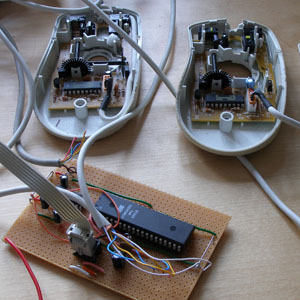
It turns out that Windows makes it rather hard to extract input from individual mice if you have several connected to your PC. It is also rather tricky to override the normal mouse behaviour of moving the Windows cursor. Therefore rather than connect the mice directly to a PC I decided to interface the mice to an AVR microcontroller. The AVR then has a serial interface to the host PC.

The PS/2 mouse interface is a bit of pain to work with, but with a bit of effort I was able to get things connected.

Start
With the electronics working I chose to use a box file as the fame for installing the mechanics. I like the idea of hiding this rather odd project inside this ordinary piece of stationary. I cut the mice to just keep enough of the PCB mounting and roller mecanism to meet my needs. For the third axis I introduced a third mouse with only acts as a mechanical frame and as a "remote" optical shaft-encoder for one of the two actually interfaced to the AVR.

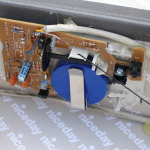
The original design uses simple weights to tension the cords. I wanted something more compact and portable. I decided to use spring-loaded retracting security badge clips. This photo shows one of the mice and the tensioning device (in fact this is the third-access without any active electronics). The cord is wrapped around the black horizontal roller and through a hole drilled in the plastic tab above the roller. As you can see HOT GLUE is an essential construction component on this project.

For the software I decided to run the calculations to get the mouse position on the AVR. This means that the results don't need further processing (except for scaling) on the host PC.

At this point a project I had thought might take a week at the beginning had taken more like a month. Still I had a 3D mouse and it actually works pretty well. The main problem is that that the data from the mice does drift leading to innaccurate absolute lenths for the location cords. As long as you don't make too sudden movements you can use it for several minutes without having to reset the reference point.

I wrote a couple of little applications in VVVV to show off the mouse both as a camera positioning tool and also as a 3D drawing tool. The problem with camera positioning though is that you have no orientation data for the mouse. You basically can look at a fixed point from different angles, but not change where you are looking. In the back of my mind I came up with a solution to fix this limitation, and I knew that I couldn't rest until the job was done properly. So, with a heavy heart I embarked on part 2 of the Three Blind Mice project.

One mouse
Three Blind Mice Part 2

The aim of part 2 was to add orientation sensing to the original design. These days you can get a lot of chip-based solutions to sense orientation (except around the vertical axis). However I had an idea which was more in line with the spirit of the original design.

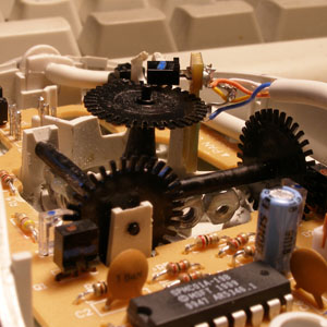
An opto-mechanical mouse has two horizontal rollers at right angles to measure the ball's motion. My idea was to remove the ball and add off-centre weights to the rollers so that gravity makes the rollers always want to orient in one position. A bit of experimentation convinced me that this idea could give good enough results to be useful. On the photo you can see the two small nuts I fixed to the rollers.

In the first stage of Part 2 I interfaced a third mouse to the AVR and doctored it as described to sense the orientation of the mouse against the horizontal plane. Amazingly it works really quite well!

The last challenge therefore was to sense orientation around the vertical axis. To do this I mounted a shaft through the middle of the mouse and connected it to a shaft-encoder. This shaft encoder was connected to the spare on one of the original mice in part 1.

Provided you can set some reference for the vertical axis in the mouse you can use this arrangement to get the mouse's orientation in all three dimensions.

I should add at this point that the maths to translate from the mouse data to its orientation is mind bending. 3D rotation about arbitrary axis is not a pretty subject.
Part 2

Phew! So, here we are at the end of the project. A full six axis 3D controller built from old computer mice. Eat your heart out Nintendo and Sony. This is the future.

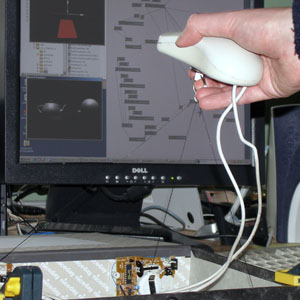
Demo software (running in background on the photo) allows the 3D mouse to control the camera view on a scene. You can pan around the scene any way and observe it from all angles. The 3D mouse is a little odd to start with, but once you get used to it then it actually becomes quite natural.

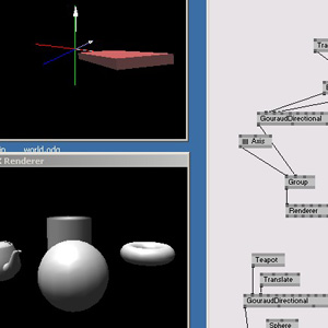
Open the full screenshot from the thumbnail on the right. In the top left window is a red box which shows the position and orientation of the mouse. In the bottom left window you see a scene viewed from the point of view of the mouse. The right hand side is a VVVV patch to create these views.


This is a project I am glad to be done with now. Much more hard work then I ever thought to start with, but I do love the fact that finally I got the results I wanted and only used scrap components.
Complete

Screenshot
Source: http://lushprojects.com/

Labels: ,

How to make videoprojector and spend 0.00$.


For the beginning we measure the sizes of a forward part of the monitor.

Then, we take a cardboard and on these sizes we make a box in height of 40-50 sm (without a bottom and one side). Now we take a lens and densely we turn a cardboard on its edges, the cylinder should turn out.


Self-made objective


Nom on the bottom of the box precisely on the center we make an aperture of such size that this cylinder could move there. We insert it there and we fix a box on the monitor.

Now all we need to do is to put the monitor on it's place and project the image on a wall
We receive the dimmy and overturned image. But, with this problem it is possible to consult. The decision - ACDSee 7.0.

Push PLAY, turn the correction of autolevels on (for increase in brightness) and we overturn the image on 180 degrees.


As a result we have received a projector almost free of charge.

How to make the grinding machine tool from Hard Drive.


We have the HDD model Seagate ST9546A Linear Speed 2.4 MB/sec 1995 of release.
What do you think, will suffice the capacity to make the grinding machine tool?

Another attempts with new HDD have failed. At one has failed the engine at the second the controller has burned down.


Here it our pre-production model - it already never will find the former life. But we that trust in reincarnation;)


We break off head HDD that it did not stir to ours test. One of the testers has damaged his hand.


You can see his blood.
We cut out a circle from an emery paper we


Paste an emery paper to a disk.


Start! Yup!! It really works! We have grinded a chisel and a knife. And now this knife we cut a doll from a strong fabric as an edge of the razor.


Look 2 minute video with this test.
How To Make The Grinding Machine Tool From Hard Drive. - video powered by Metacafe


This thing but next time I'll tell you how to overlockinf CPU in 10 times faster


Labels:

How to make a Coin Ring (Easy Steps)


This is the way I make a coin ring. You can do
it different ways depending on the tools you have available. So here it
goes!


First you need a piece of steel to use as a base
for the coin to set on. Take the coin and stand it on edge. Tap the
reeded edge with a spoon or a small machinist hammer while continually
rotating the coin, I would recommend using the spoon first until you get
the hang of how the silver feels when it folds. Be patient and don't
rush it, it takes a while.


Once I have the letters on the edge of the coin
folded in that's where I stop and then take a look at the coin and make
sure it's round and the edges are even.


Next take and drill a hole in the center of the
coin. Once the bit goes through the coin it will jam itself on the drill
bit. Leave it on the drill bit.


Next take a piece of sandpaper( I use 400 grit
to start) and hold it against the coin as you run the drill. You can
sand all the dings out of it this way. I then use 1200 grit to finish
it.


Then I take some "Brasso" and put it in a cloth.
Then run the drill with the coin spinning on the cloth. Do this as many
times as you want(use a new spot on the cloth and Brasso each time)
until your satisfied with the shine of the ring.


Next take the coin off the bit and place it in a
pair of vice grips. I use the vice grips with the curved jaw as this
will hold the coin better than the straight jaw vice grips. Make sure
you wrap something like heavy tape around the teeth of the grips. If you
don't you will be sorry. If you have some clamps with rubber or plastic
on the contact points this will work also.


The next step I take a dremmel with a cutting
bit and route out the center of the coin. Be careful as the bit will
jump around if you don't hold it tight. Take your time! Once you get
close to your proper size you want then stop.


I then take a sanding disc and smooth out the
inside and stop at the size you want.


Next step take a buffing wheel and put some
Brasso on it, and then run the dremmel buffing out the inside of the
coin. Do this a couple times. Thats about it! Give it a shot, it takes
time but sure is neat when it's done.

HH

Don/Michigan


Source: http://cleanstream.net/mirrors/coin_ring/

Labels:

How to Make a Folded-Paper CD Case


Instead of paying good cash for cd cases, which eventually break and end up in a landfill, how about creating your own, unique folded-paper cd cases that are biodegradable and take up a fraction of the space?

The Props:

8 ½" by 11" paper

a cd

a computer (optional)

labels (optional)

The Procedure:

1. Center a cd, which you’ll be using as a guide, at the top of a sheet of paper, as shown.

2. Fold in sides of paper to sides of cd.

3. Center cd at the middle of the folded paper.

4. Fold bottom up.

5. Fold the horizontal creases, which I’ve identified in red, to sides as indicated by arrows, so the creases are even with sides of original folded sides. (I’ve identified the creases in question with dashed lines for illustration.)

6. You'll have a box-shape sticking up toward you after making the folds in step 5. Just fold this flap down flat as shown below.

7. Tuck the "ears" that are sticking out to the sides in between the original side folds and the fold created in step 4.

8. Slip cd into front pocket and fold down top half of paper.

9. Dog-ear the top two corners of the top half of paper.

10. Slip top half of paper into pocket.


For a personal touch, print labels and photos on the front center of paper to give your cd holder some pizzazz. A picture from a trip of a lifetime or a friend’s favorite tunes.

Print the name of that book you wrote or are working on. Any paper, of course, will do including postal wrap, grocery bags or something of the decorative variety. A sheet of heavier-weight wrapping paper with a printed label makes a great way to store and share holiday pictures.


 Sourse: http://www.curbly.com/DIY-Maven/posts/680-How-to-Make-a-Folded-Paper-CD-Case

Labels: , ,